
Interested in a Similar Solution?
Tell us about your product and capacity — we will prepare a tailored proposal for your application.
Ask About This Solution →Hot food cooling and fruit and vegetable pre-cooling are two different things. Fruits and vegetables are pressed down from ambient temperature after harvest, while hot food is pressed down from a high temperature of 90°C. A batch of braised meat or a tray of cooked food comes out carrying a large amount of sensible and latent heat, and the cooling rate directly determines how long it can be stored and how far it can travel.
This project is in Indonesia, and what it does is turn “hot food cooling” into a process step that can be timed on the production line: a single batch of 1,000 kg of cooked food, cooled from 90°C to 10°C, with the cycle held within 20 minutes.
Project Background
The customer is a food processing enterprise in Indonesia, producing braised meat, cooked food, and fast-food products, with the material specific heat calculated at 3.6 kJ/(kg·K). The production line output temperature is around 90°C, and after output the entire batch needs to be cooled quickly and evenly to 10°C before entering subsequent processes.
Indonesia has a tropical climate, and the scheme is calculated based on a wet-bulb temperature of 28°C. The entire line is configured with 34 units of CVF-1000 class (single-batch 1,000 kg tier) vacuum rapid coolers, adopting a two-stage water capture plus centralized liquid supply system form. The scheme was finalized in June 2026.
Site Challenges
The first is the hot and humid environment. With a wet-bulb temperature of 28°C, the normal-temperature water that the cooling tower can provide is in the 32/37°C range. This water temperature, against the high-temperature, high-humidity water vapor inside the chamber, makes it difficult for single-stage water capture to catch all the water vapor in one pass. The remaining water vapor all falls to the vacuum pump, which drags out the cycle and makes it unstable.
The second is that the heat load is concentrated in the period when the chamber is opened. When 90°C material first enters the chamber, evaporation is at its most intense, and the instantaneous water vapor volume is at its maximum. If a single large machine is selected based on the maximum load across the entire cycle, that machine will be idling at low load for most of the cycle.
The third is the line takt. The 34 units need to run continuously according to the production line takt. If cooling water, secondary refrigerant, and vacuum were each equipped with a separate set per unit, the plant room and piping would spiral out of control; centralized liquid supply and centralized monitoring are the prerequisites for this scheme to be implemented.
Scheme and Configuration
The scheme is configured with 34 units of CVF-1000 class vacuum rapid coolers. Each unit has a primary water catcher connected to normal-temperature water and a secondary water catcher connected to -5°C calcium chloride (CaCl₂) secondary refrigerant, with the two stages in series and centralized liquid supply.
| Item | Configuration |
|---|---|
| Equipment model | CVF-1000 (1,000 kg/batch capacity tier) |
| Single-batch processing capacity | 1,000 kg/unit (design maximum five carts 60 trays × 20 kg = 1,200 kg) |
| Processing time per cycle | ≤ 20 minutes |
| Cooling range | 90°C → 10°C |
| Evaporated water volume | 6~10%/batch (source file value, including latent and sensible heat) |
| Primary water catcher heat load | 220 kW/unit |
| Secondary water catcher heat load | 45 kW/unit |
| Refrigeration compressor | Hanbell RC-2 screw compressor, cooling capacity 255 kW (@ -10/40°C), input 70 kW |
| Vacuum pump | Water ring pump 300 m³/h (11 kW) + rotary vane pump 300 m³/h (7.5 kW, one duty one standby) |
| Primary water capture condensing side | Normal-temperature water, 32/37°C counterflow cooling tower supply |
| Secondary water capture secondary refrigerant | -5°C CaCl₂ solution (25% concentration, 0°C return liquid) |
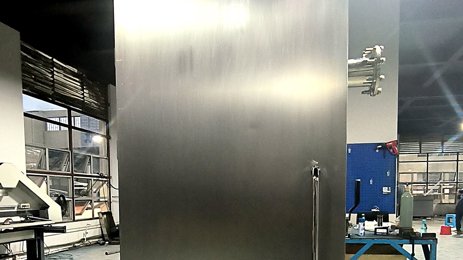
| Vacuum chamber specifications | Volume 6.8 m³ (internal dimensions 1.0 × 3.4 × 2.0 m), 304 stainless steel, double translation doors |
| Entire line and control | 34 units as a complete set, including central monitoring |
| Implementation and warranty | 18-week implementation plan; 12-month warranty |
The system runs a two-stage route: after the material cart is pushed into the vacuum chamber and the doors are sealed, the water ring pump first pre-evacuates the chamber to 10 kPa. In this stage the water vapor volume is large and the temperature is high; the water ring pump is resistant to high temperature and high humidity, so it first carries away most of the water vapor. After the pressure drops, the rotary vane pump is started, and at the same time the cooling water valve of the primary water catcher is opened, so that the primary water catcher uses normal-temperature water to first condense a large amount of water vapor into water. Once the primary outlet temperature drops below 40°C, it switches to the secondary refrigerant, which catches the remaining low-load water vapor and continues pumping until the material core temperature reaches 10°C.
The benefit of separating the primary and secondary stages lies here: the large load in the high-temperature stage is borne by the normal-temperature water stage, which has a large heat exchange area and low water temperature requirements; only the small remaining load in the low-temperature stage is handed to the -5°C secondary refrigerant, and the secondary stage only needs 45 kW of cooling capacity. The entire refrigeration system is configured at 220 kW plus 45 kW, rather than using one large machine to carry all the way from 90°C to 10°C—equipment investment redundancy is small, and the operating load also fits the process curve more closely.
The water catcher is the prerequisite for this process. If water vapor is not condensed into water inside the chamber, the pressure cannot be maintained, and the cycle will keep rising; the cooling capacity must also be continuously carried out of the equipment by the refrigeration system, otherwise the water catcher itself will saturate. The task of the vacuum pump here is to extract non-condensable gases and maintain the pressure at the level corresponding to the endpoint temperature. For the complete product and common configurations of food vacuum rapid coolers, see the food vacuum rapid cooler product page.
Performance Data
According to the scheme configuration, the core indicators of this system on the project side are:
- Single-batch processing capacity: 1,000 kg/unit, design maximum 1,200 kg (five carts 60 trays × 20 kg);
- Processing time per cycle: ≤ 20 minutes;
- Cooling range: 90°C → 10°C;
- Evaporated water volume: 6~10%/batch (source file value, including latent and sensible heat);
- Vacuum chamber: 6.8 m³, 304 stainless steel double translation doors, 34 units as a complete set, including central monitoring.
The entire cooling process is completed inside a sealed vacuum chamber, with no contact with outside air. The same batch of material is consistent from start to finish, without manual turning. The chamber uses 304 stainless steel double translation doors, and material carts enter and exit as whole batches, so the operational workload on the production line side is concentrated in the cart entry and exit stage.
Note: This project case card does not separately record the water loss rate indicator or item-by-item measured values of material inlet temperature; the inlet temperature is taken as the hot food 90°C recorded in the source file; the ultimate vacuum degree of the vacuum chamber, the water loss rate per unit, and the final number of equipment units are subject to the order confirmation document.
Summary
What is truly difficult about hot food rapid cooling is not “bringing the temperature down,” but “bringing every batch down according to takt and to the same endpoint.” In a tropical environment with a 28°C wet bulb, 90°C high-temperature inlet material, and a 34-unit line takt, any single-stage configuration at any point in the process will lose efficiency. By splitting water capture into two stages—normal-temperature water and -5°C secondary refrigerant—and making the liquid supply a centralized plant room, this scheme can deliver 1,000 kg of cooked food from 90°C to 10°C within 20 minutes.
If your production line also has hot food queuing for cooling after output, you can send us the single-batch weight, output temperature, target endpoint temperature, and number of batches per shift, and we will carry out configuration calculations based on actual working conditions. For similar food factory rapid cooling and origin pre-cooling cases, see our customer case collection; for specific configuration discussions, contact us.
Interested in a Similar Solution?
Tell us about your product and capacity — we will prepare a tailored proposal for your application.
Ask About This Solution →